
Srpski
RTpS-400/2 TAM-110
K-15 RTpS-400/2
K-15 RTpS-400
RD-3 K-3/K
RP-4 UP-1 TgKG-1 ETL-1
RTU-400/V
AT-5A AT-37
AD-3.7
RTpS-400/2

Description of the HF radio teleprinter system RTpS-400/2

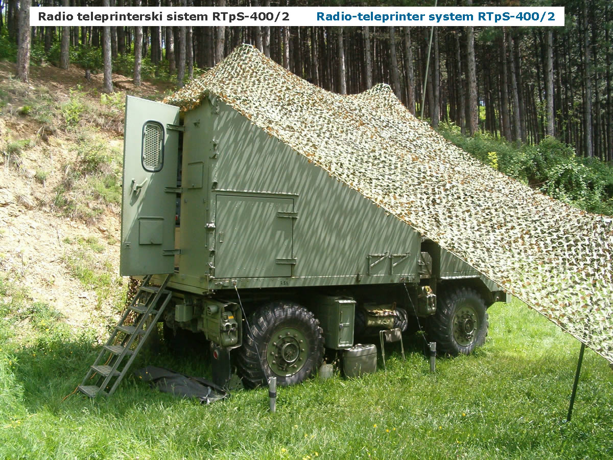
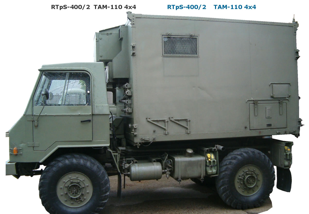
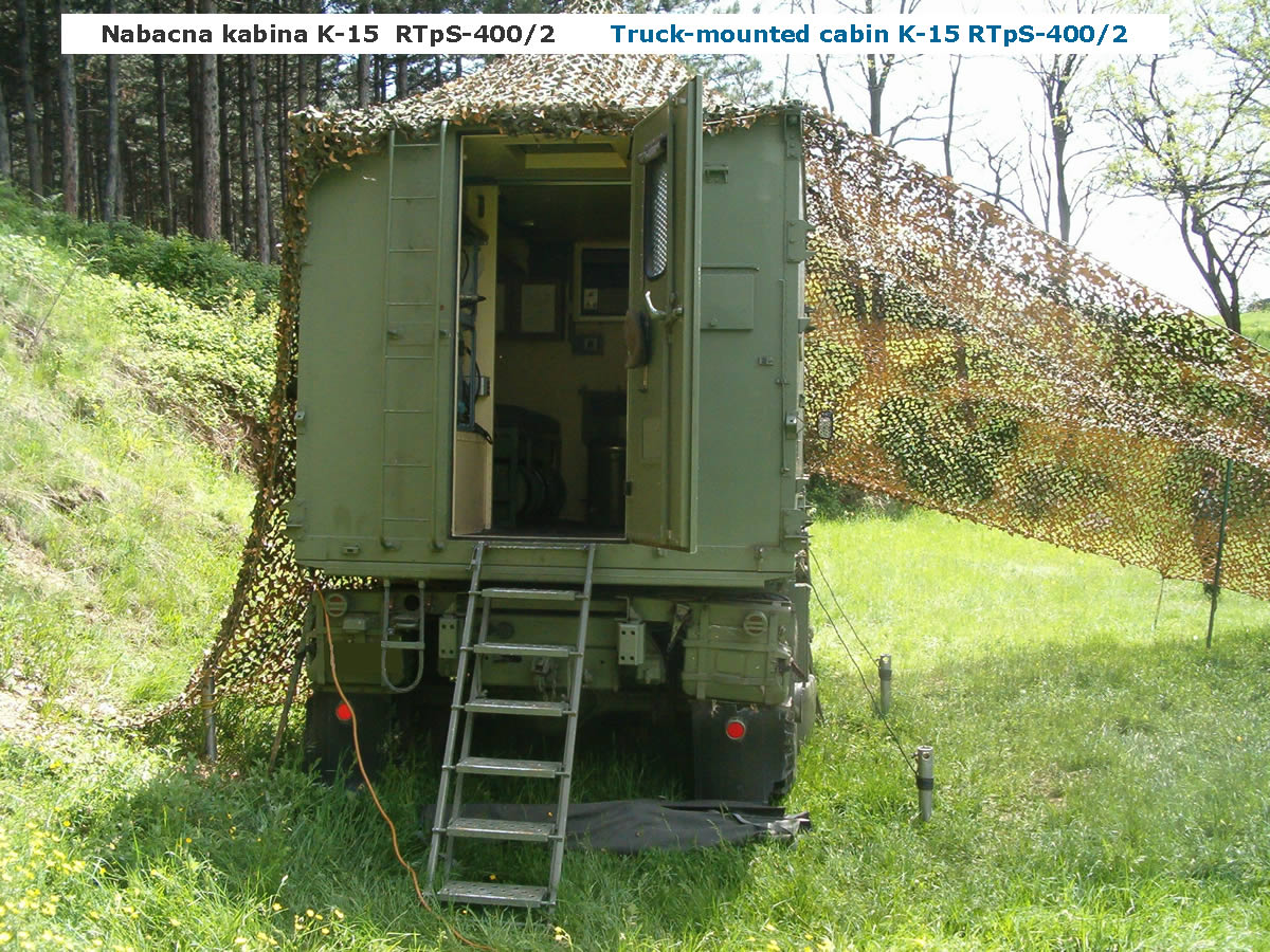
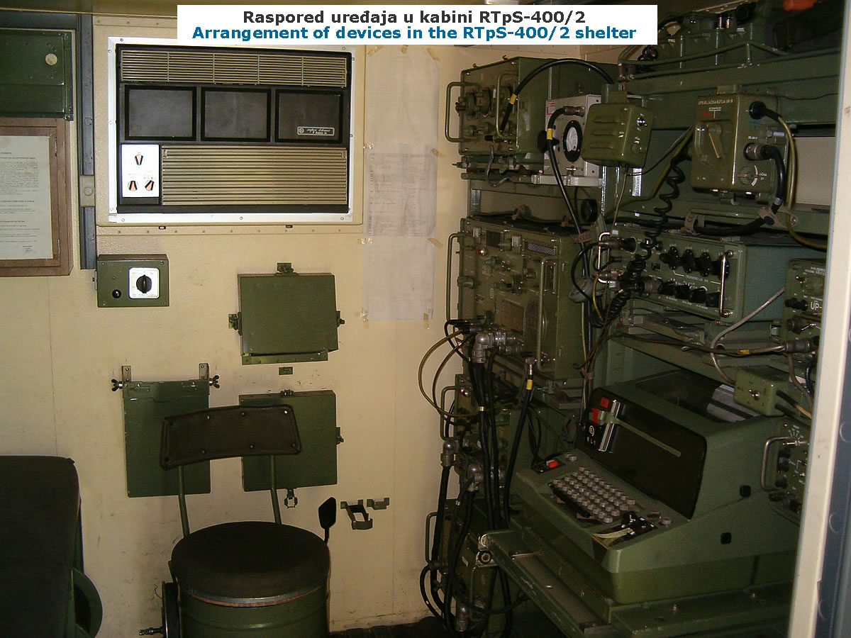
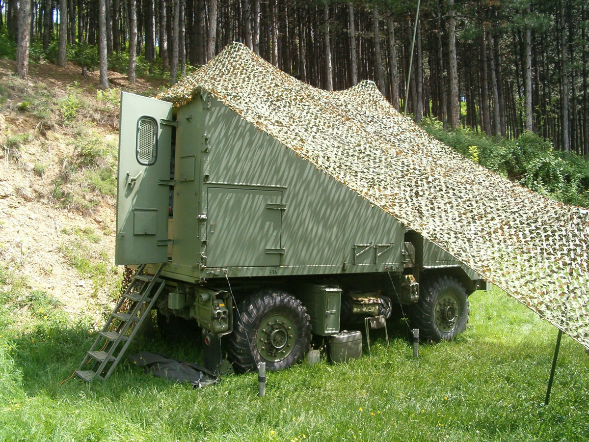
RTpS-400/2Radio-teleprinter system RTpS-400/2 was installed in the K-15 shelter cabin of the TAM-110 T7 BV (4x4) motor vehicle and was a more modern version compared with RTpS-400/1 (on the TAM-5000D vehicle). In addition to basic simplex operation, the system provided full duplex information transfer in the HF frequency band from 2 MHz to 12 MHz when it was remote-controlled from a receive signal centre. It was connected to the receive signal centre by coaxial cable KS-140 at a distance of up to 1.5 km.

There was also a capability to operate on the move: its transmit-receive whip antenna AT-26 was bent rearward with the guy ropes, and power was supplied from its Diesel generator set AD-3.7, which was pulled out of its compartment and secured on the mounts — skids. This was used only in extreme necessity during rapid displacement, because the generator set was exposed and could be damaged. The noise from the generator set inside the cabin was enormous.

Modes of operation were SSB (LSB) and AM telephony, Morse-code CW telegraphy, and teleprinter telegraphy RTTY. The transmitter output power over the entire band is 450 W for CW and RTTY, 500 W PEP for SSB and 120 W for AM operation. On lower frequencies it reached up to 600 W PEP.

For the crew of this system only the best soldiers of the radio-teleprinter specialty were carefully selected. Without any exaggeration, those men represented the very elite and pride of the entire Signal Corps. That unbreakable bond with the equipment and the profession lives on to this day, and even after many years every former crew member proudly states that he served his military service precisely on the Radio teleprinter system RTpS-400.

° Functional assemblies, equipment and component parts of the RTpS-400/2 set:
Transmit section

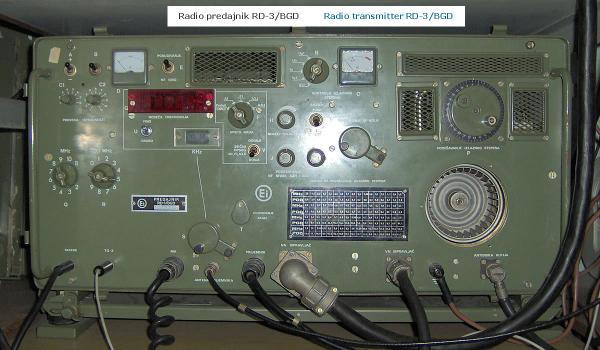
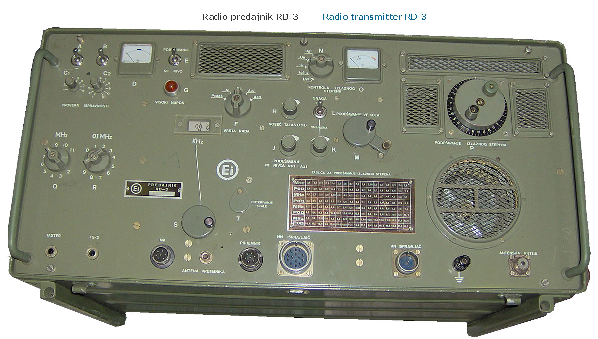
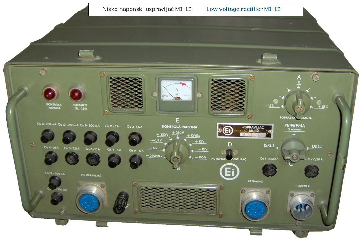
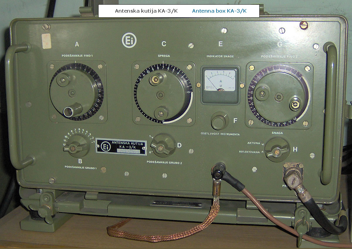
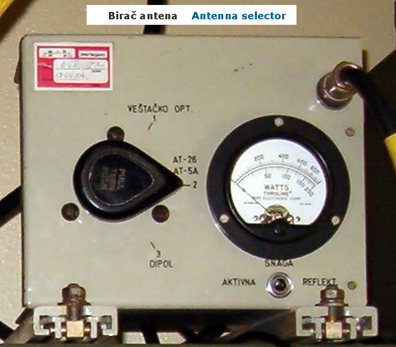
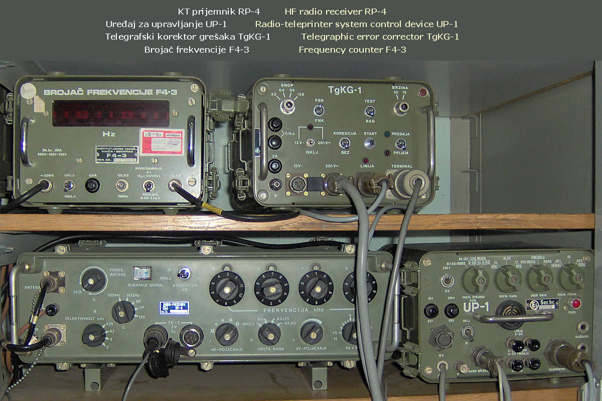
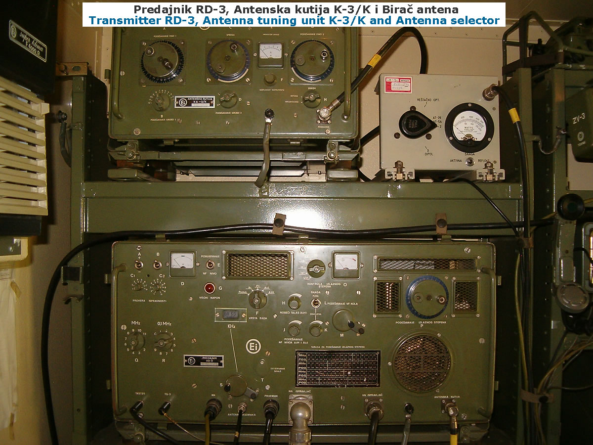
Transmitter RD-3/BGD built in vacuum-tube technology. Compared with the older Transmitter RD-3 , its VFO oscillator is thermally stabilized and a display was added showing the frequency in kHz (0–100 kHz). Anode voltage for the output tubes (2 x 4CX300A) was provided by the high-voltage rectifier MI-11, and the other voltages by the low-voltage rectifier MI-12. For matching the transmitter output stage to the antenna the antenna box K-3 was used. Antenna selection was made with the antenna selector, and the accuracy of the transmit frequency was checked with the frequency counter F4-3

Receiver and VHF set

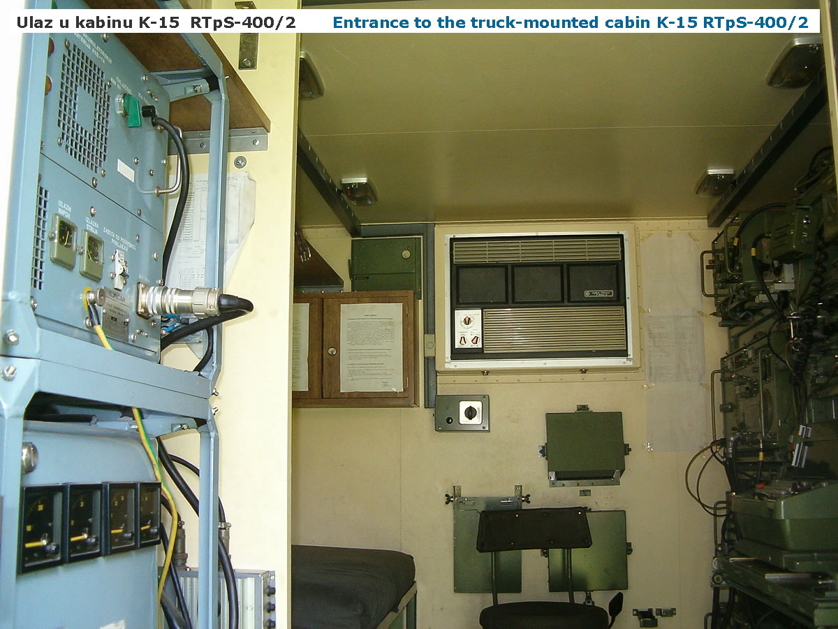
Reception was provided by the HF radio receiver RP-4 manufactured by RIZ Zagreb, and official VHF communications by the VHF radio set RU-2/1. Both sets were powered from the low-voltage rectifier MI-12 or by DC from the K-15 cabin battery 24 V (2 × 12 V / 135 Ah lead-acid batteries).

Telephone and telegraph equipment and accessories

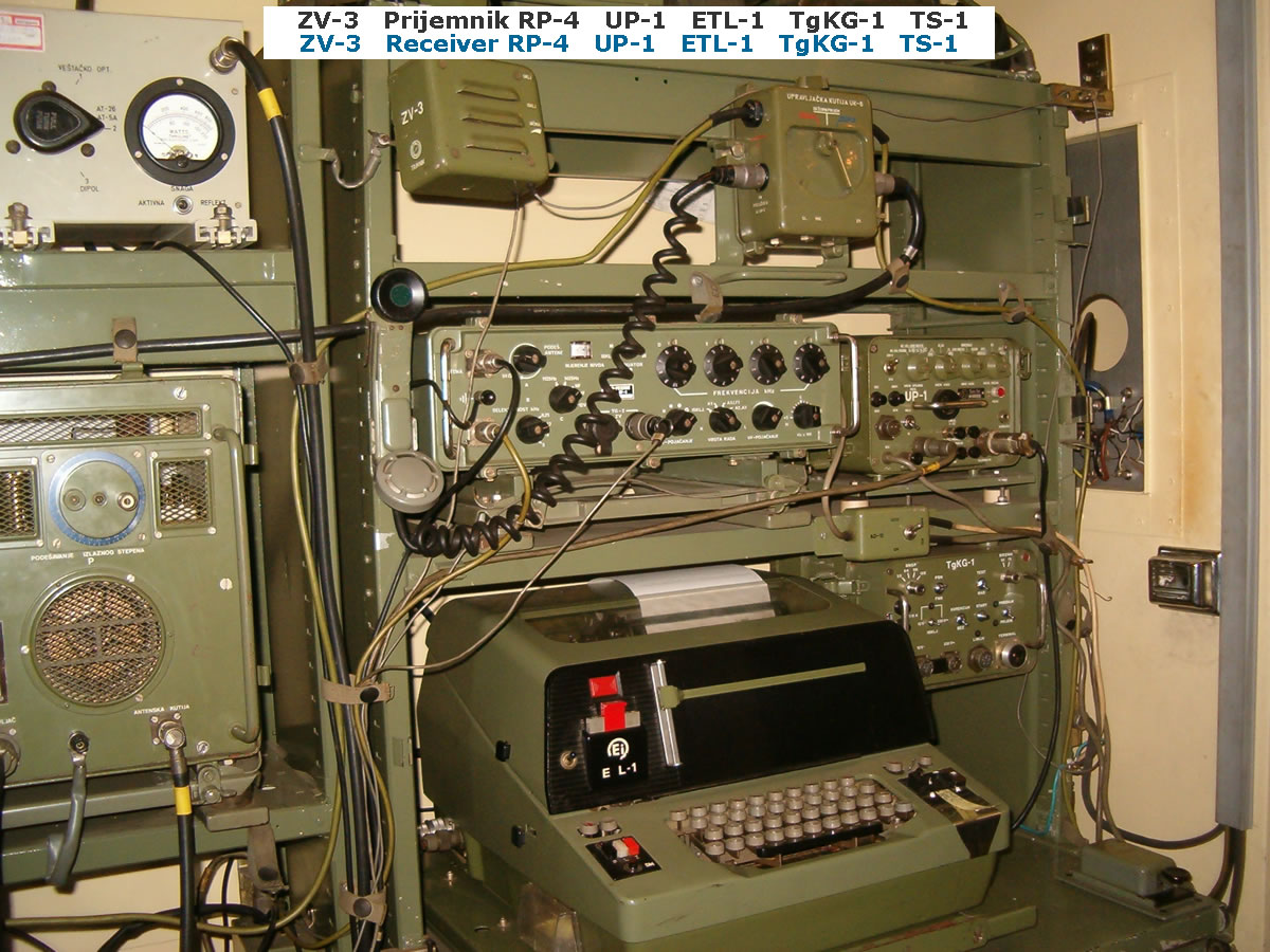
For receive and transmit of teleprinter telegraphy RTTY the electronic teleprinter ETL-1 manufactured by EI Niš was used. As the teleprinter modem the control unit UP-1 was used. On receive, error correction was performed by the telegraph error corrector TgKG-1. For receive and transmit of telephony and Morse telegraphy the following accessories were used: telegraph key TS-1, handset MTK-1, headphones SL2 and loudspeaker ZV-3. For the telephone wire service link the set included two field telephone sets M-63.

Antennas

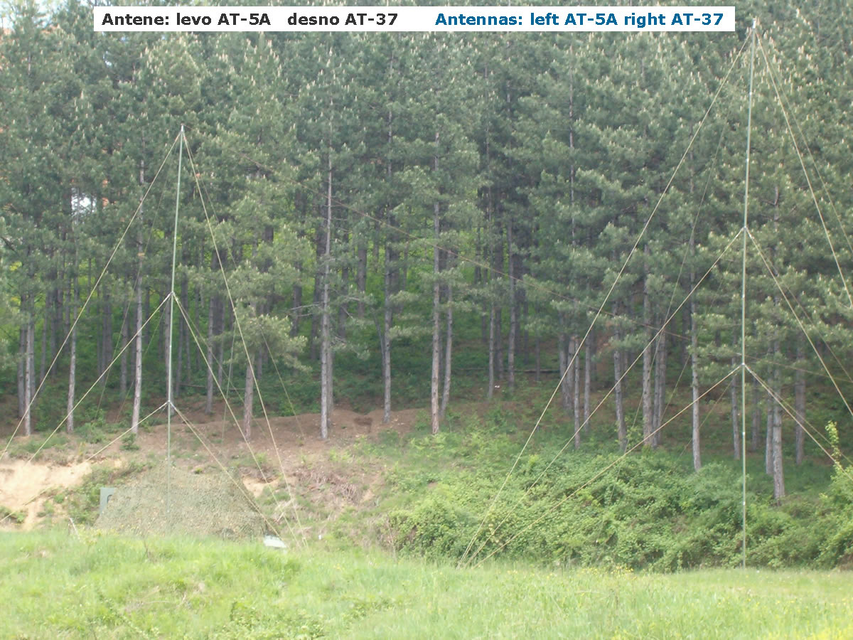
Wire transmit-receive antenna AT-5A was used as a quarter-wave antenna for operation in the band from 2 MHz to 12 MHz, transmit-receive whip antenna AT-26, broadband receive antenna AT-37 and transmit-receive whip antenna AT-59 for the VHF radio set RU-2/1.

Power supply

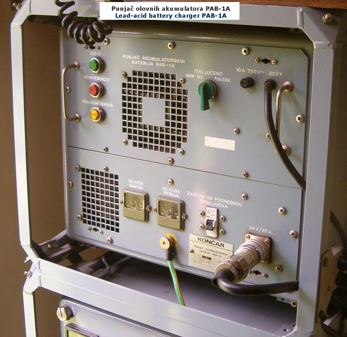
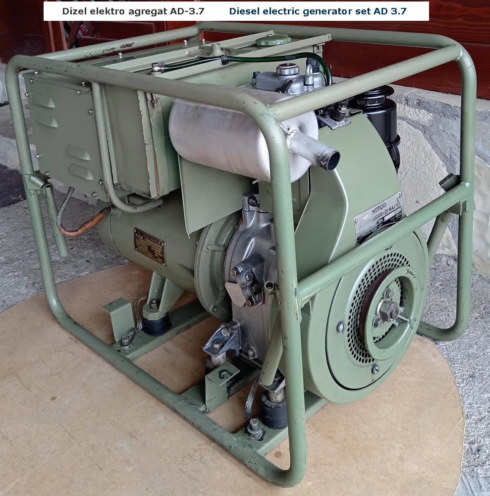
The system was powered by 220 V / 50 Hz AC from its Diesel generator set AD-3.7 or from the mains. The power consumption of RTpS-400/2 was 3.5 kVA, and the generator set AD-3.7 could provide 3.7 kVA in continuous operation. When the generator set was not running, the system was also powered by 24 V DC from the battery of the K-15 shelter cabin (2 × 12 V / 135 Ah lead-acid batteries). They were charged via the charger PAB-1A.

Line accessories

Coaxial cable KS-140, 6 reels totaling 1,500 m in length; two-conductor field telephone cable PTK-56, 2 reels totaling 500 m in length; and cable drum DB-4.

Other

Motor vehicle TAM-110 T7 BV (4x4) with shelter cabin K-15, air-conditioning unit F4000D, heater unit JUGOVEBASTO, distribution panel ORP-3, isolating transformer, 4 earth rods ZM-1 and cables: interconnecting, power and coaxial.