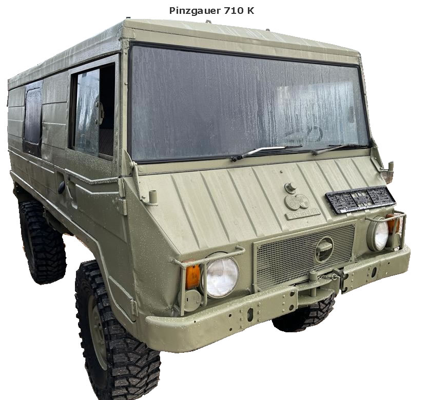
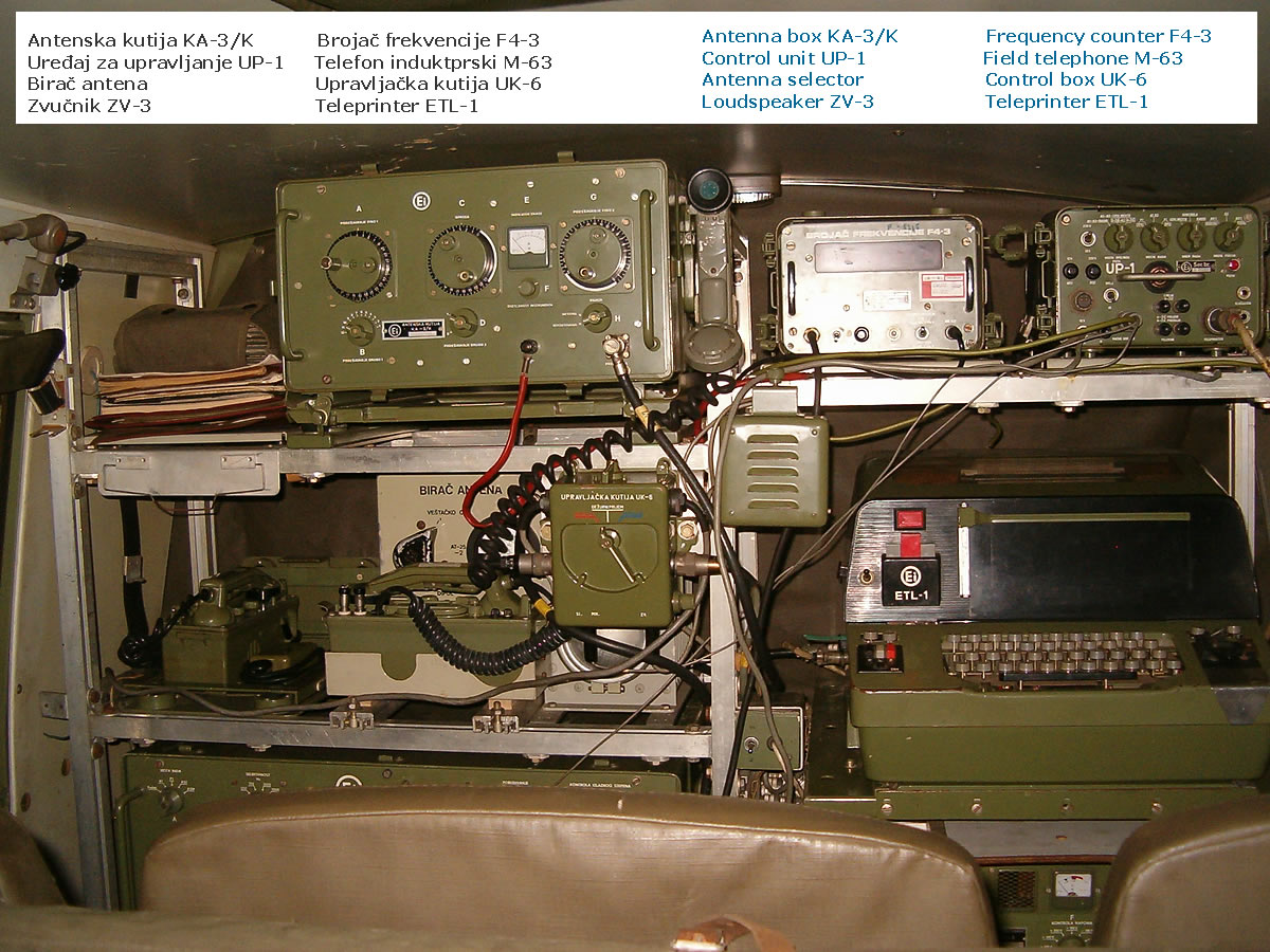
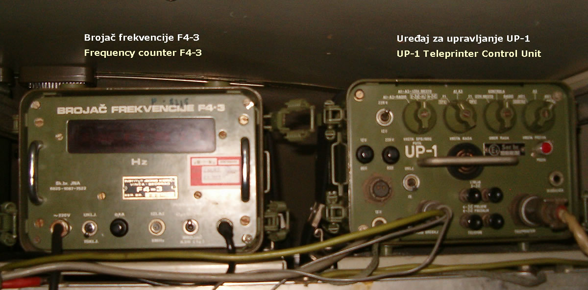
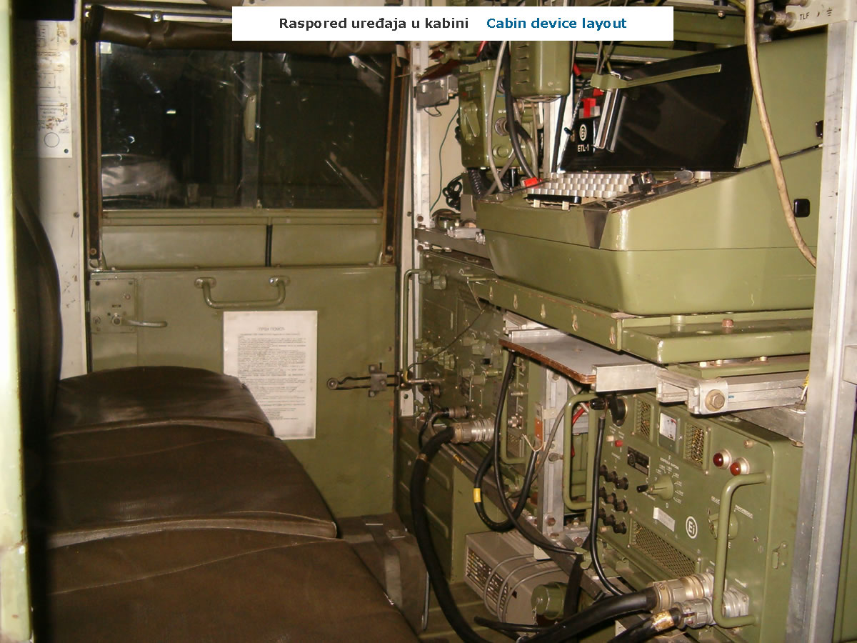
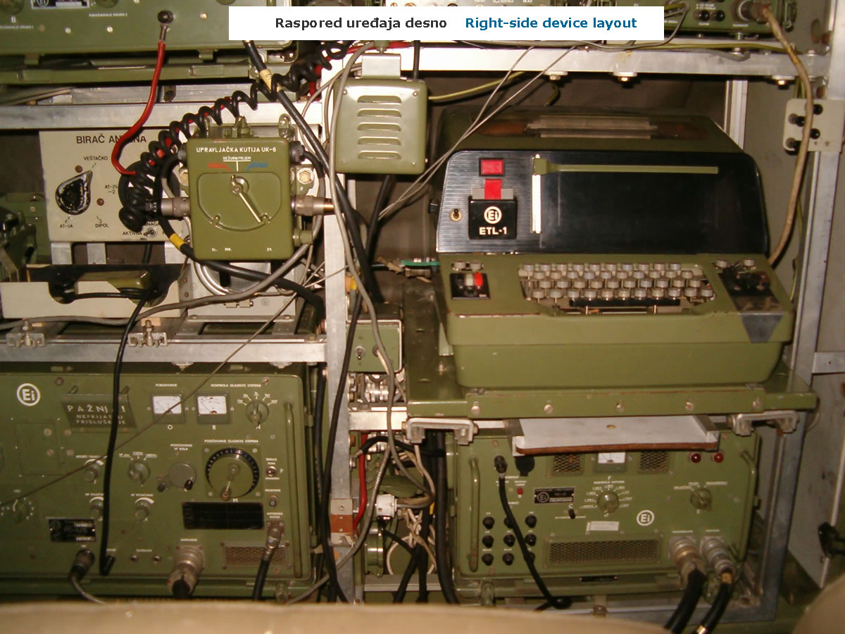
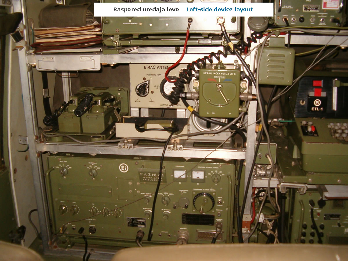
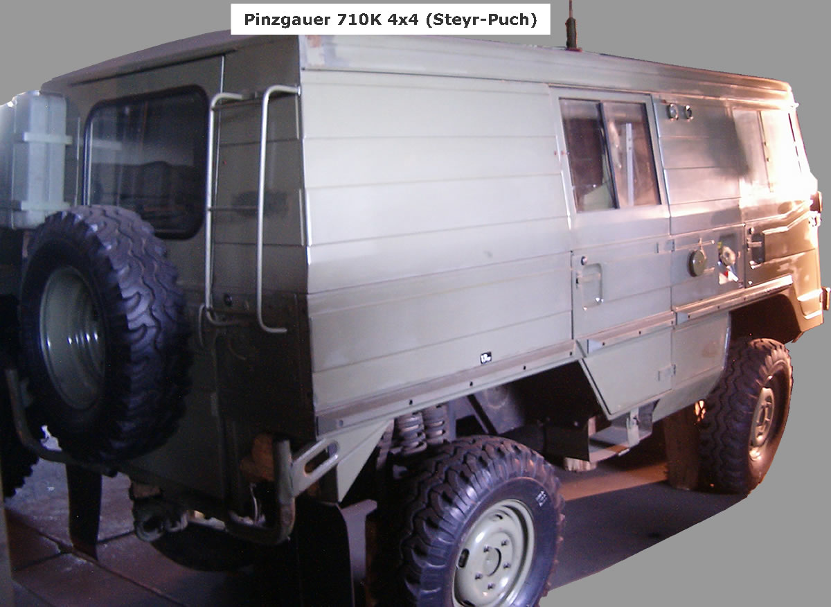
Radio-teleprinter set RTU-100/V was installed in the field vehicle Zastava AR-55V and trailer Zastava D-2V of 0.5 t payload capacity. The vehicle and trailer were produced at the automobile factory "Crvena zastava" Kragujevac in cooperation with the Italian company Fiat. In the same vehicle the station crew was also carried, consisting of three radio-teleprinter operators and a driver. The space with the driver and co-driver seats was separated by a canvas cover from the rest of the cabin. All parts of the system in the vehicle cabin were fastened to the steel frame, mounting frames, floor and cabin walls.
In addition to the vehicle and trailer, the Radio-teleprinter set RTU-100/V comprised:
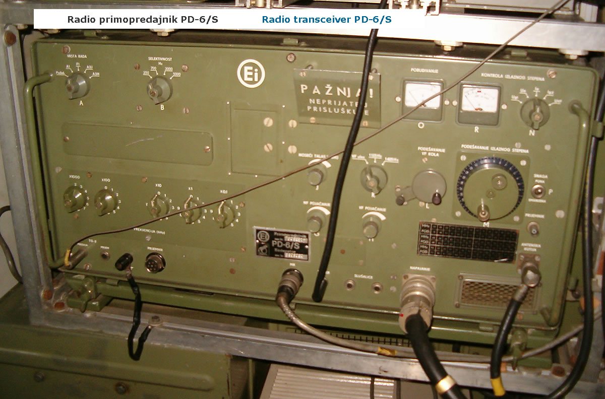
Transceiver PD-6;
- it was built into a separate aluminium housing and is characterized by modular construction. The receiver and transmitter used common circuits, so it operated in simplex. In the transmitter, an output power of 150 W (PEP) was provided by 4 powerful pentodes QE 05/40, and in the modulator a mechanical filter at 455 kHz was used. Receiver selectivity was determined by 4 crystal filters at 455 kHz with selectivity of: 250 Hz, 700 Hz, 3000 Hz and 5000 Hz. The frequency was set in combination: with two switches in steps of 100 kHz and a variable oscillator 0–100 kHz. Frequency stability was 300 Hz, and this would later prove to be a major shortcoming for RTTY operation.
 Antennas and antenna accessories; Antennas and antenna accessories;
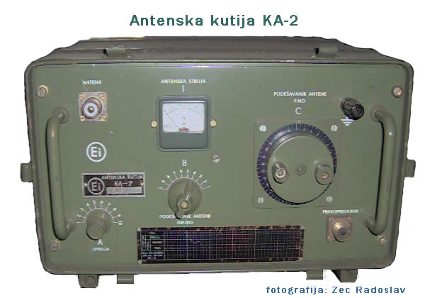
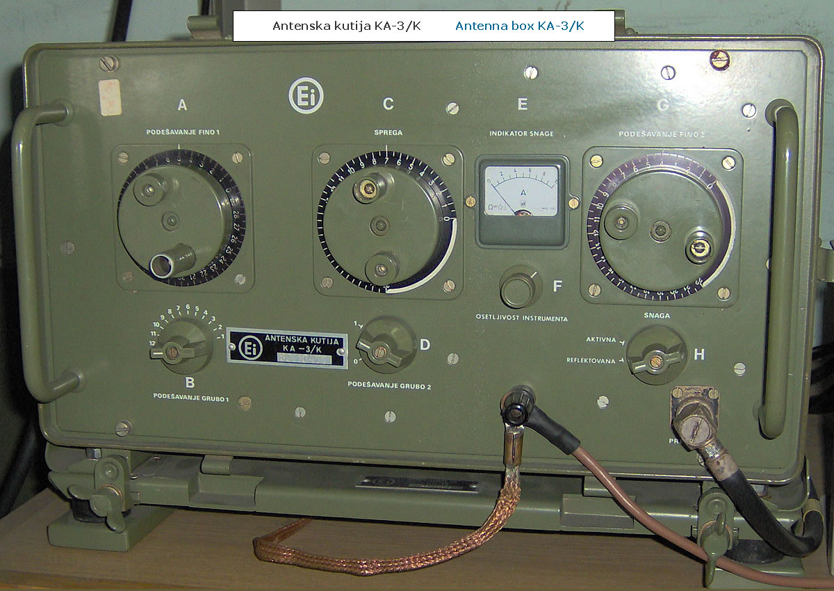
- Antenna box KA-2 was also built into a separate aluminium housing and served for matching the transceiver to whip antenna AT-16.
- wire antenna AT-5 was used as a quarter-wave antenna for operation in the band from 1.5 MHz to 12.5 MHz. It was erected when the full range of the set was required and when frequent displacements were not planned. Its set comprised: an antenna mast of 8 tubular aluminium sections with a total height of 12 m, a joint with pin and antenna insulator, antenna wire 41 m long, 12 guy ropes for guy-ing, coaxial cable KK-10 12 m long for connection to the set, and other parts for erection and packing. On the march it was carried in the trailer in two packs. The sections and guys in a separate carrier-cover, and the smaller accessories in bag TB-21. The weight of the set was a full 34 kg, and its erection required a trained and well-drilled crew, so a more suitable solution was sought, but it nevertheless remained in the system set to the end.
- whip antenna AT-16 was used for transmit-receive at the halt and for receive on the move and consisted of an antenna base and five sections totaling 4.7 m in length, a guy rope and a packing cover. It was mounted on the rear left side of the vehicle cabin. When operating with it, the declared range was reduced by 20%.
Power sources;
- Mains rectifier MI-8 provided all voltages required for operation of transceiver PD-6 when RTU-100 was powered by AC 220/110 V. When a 12 V lead-acid battery was used as the source, it operated as a voltage converter and provided voltages for the receiver section of transceiver PD-6. It was housed in a separate casing closed with a cover.
- Battery charger rectifier MI-9 was housed in a separate box and served for charging the 12 V / 70 Ah lead-acid battery and for powering the remote keying and modulation unit UK-3. Powered by AC 220/110 V. Maximum battery charging current 6 A.
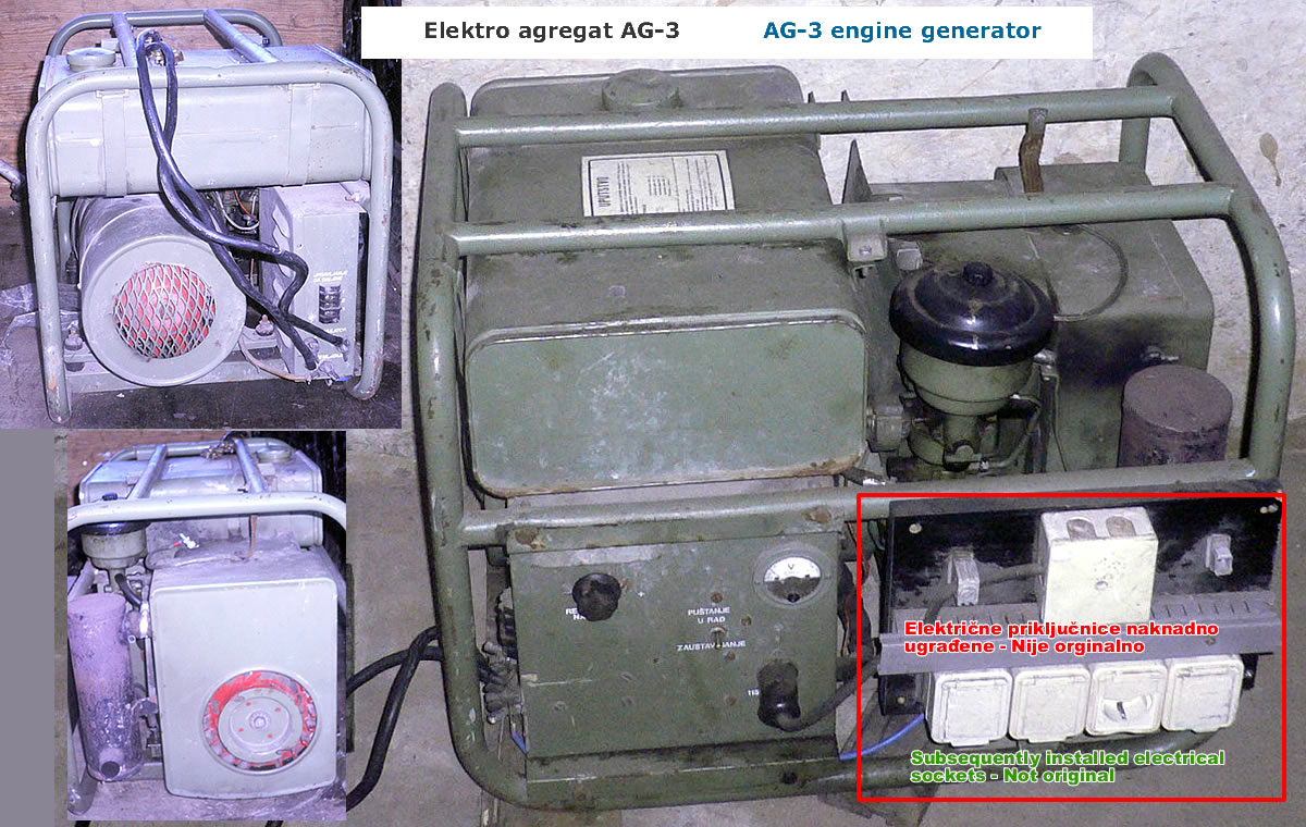
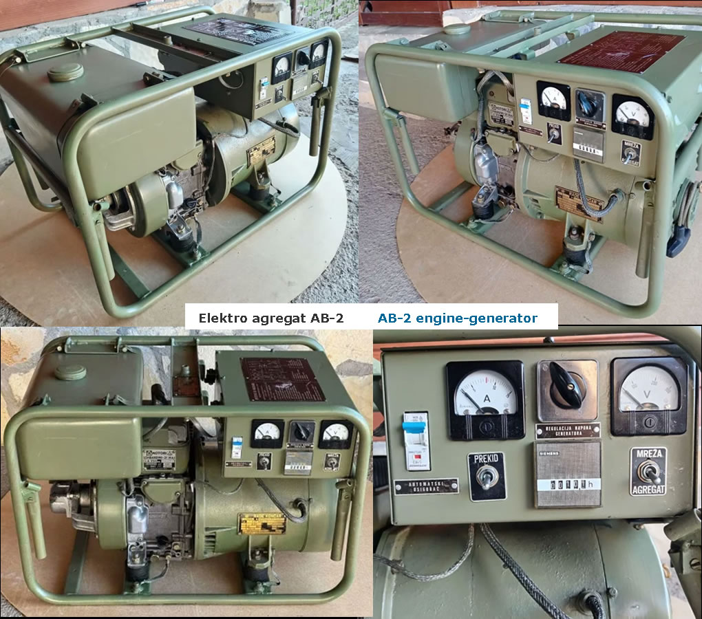
- Generator set AG-3 powered all consumers in the radio-teleprinter system with AC 230 V 50 Hz at a maximum power of 2 kW. Its set also included a 12 V / 135 Ah lead-acid battery. The same battery served for starting the generator set. It was topped up from the generator set itself with DC 14 V / 2 A. It used petrol as fuel and was transported in the trailer.
- 12 V / 70 Ah lead-acid battery powered the receiver of transceiver PD-6 when operating on receive on the move. It was placed in a housing under the driver's seat.
- distribution boxes KR-4 and KR-5 served for distributing voltages within the teleprinter system, and a 5-core power cable KE-6 30 m long brought AC 220/110 V from the generator set.
Equipment and accessories for radio-teleprinter operation and remote control;
Most of these sets are described on the page about telephone and telegraph equipment. They comprised: teleprinter Siemens T-68D or "EI" Niš ET-1, telegraph transceiver TG-2, telegraph transceiver TG-1, telegraph-telephone filter FL-1, Feld telephone M-63. For remote control with the magneto telephone M-63 or for keying the transmitter in continuous-wave telegraphy operation, in front of transceiver PD-6 it was necessary to connect the keying and modulation unit UK-3. Also for this purpose the system set included two reels of cable PTK-56 of 750 m each (total 1.5 km) and reel ML-1.
Operating accessories;
Operating accessories serve for keying and modulation on transmit or for converting the electrical energy of received signals into sound. The accessories comprised: telegraph key TS-1, handset MK-1, headphones SL-2 and loudspeaker ZV-1.
In addition to the above, the radio-teleprinter set RTU-100/V included accessories for mounting the equipment in the vehicle, auxiliary equipment for packing the gear and spare parts, various power and interconnecting cables, earth rod ZM-1, engineer tools (shovel and pickaxe) as well as a small staff tent for accommodating the crew. |